
Construction
TZR125 Track Bike > Running on 3MA electronics > Running on 3MA3 electronics
Let the 4DL engine run on 3MA3 electronics thats the idea, this should be posible as the 3MA3 electronics uses only a 12V supply and a pickup pulse.
There is certainly a challenge but that is doable, the TZR 4DL pickup location is different compared to the TZR 3MA location so this needs to be set correct.
Also lob location and length will be a challenge.
Why let the engine run on 3MA3 electronics?
1) For study purpose (bypassing the electronic restrictions)
2) For the mechanically/electrical challenge
3) For the special look (as I'm still 3MA minded)
4) For performance wise (as the ignition curves are well known specially the 0 curve could be a very good setup)
Lets start working.
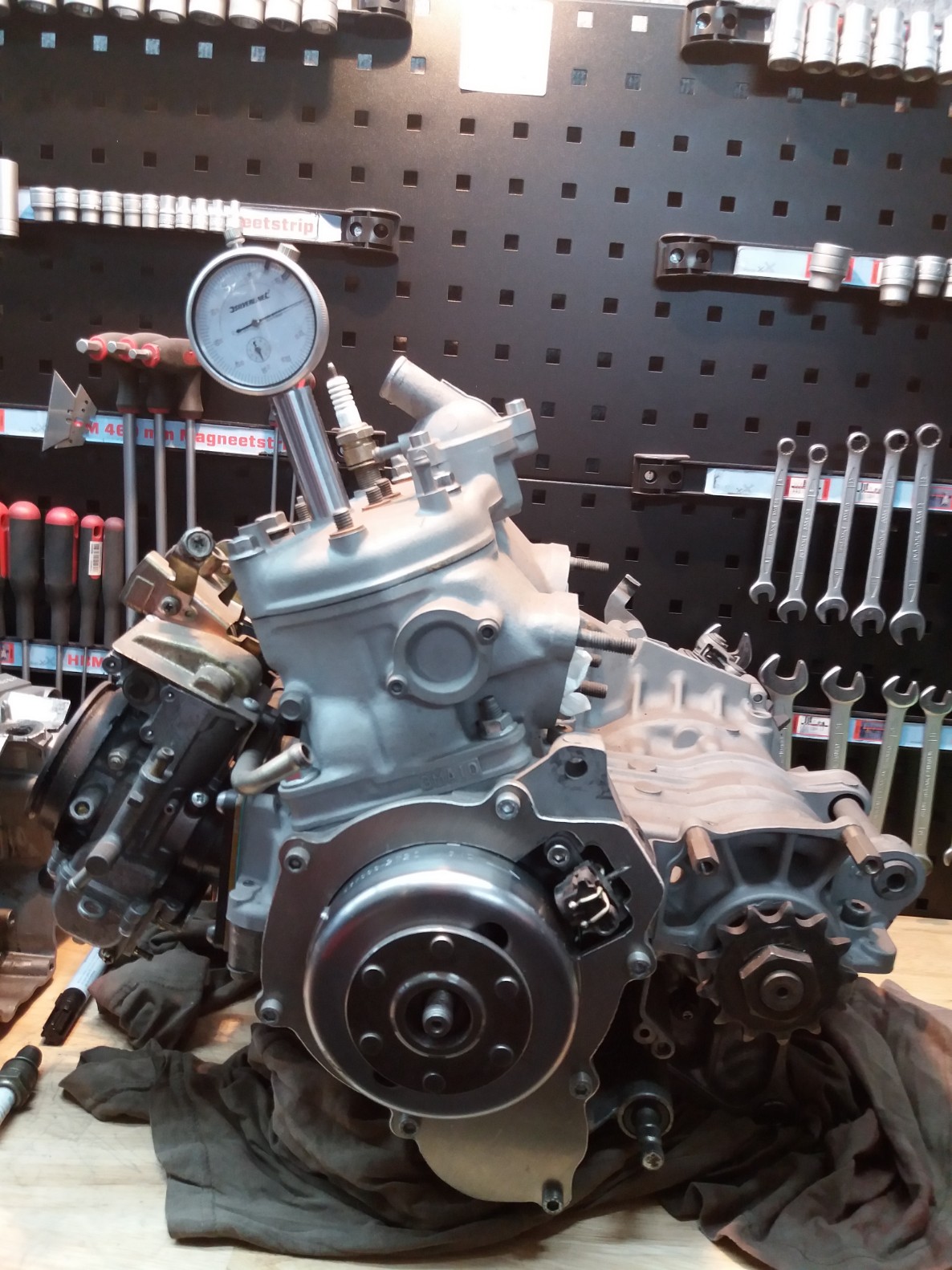
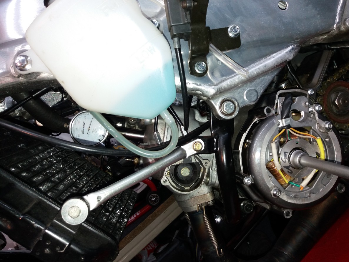
Measuring the flywheel lob length/position compared to TDC, with the use off a timing clock
Measured 2,1mm from TDC to end flywheel lob
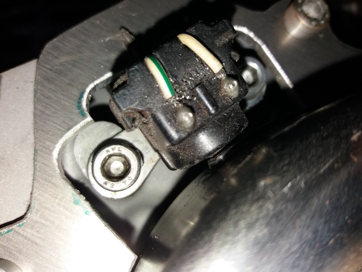
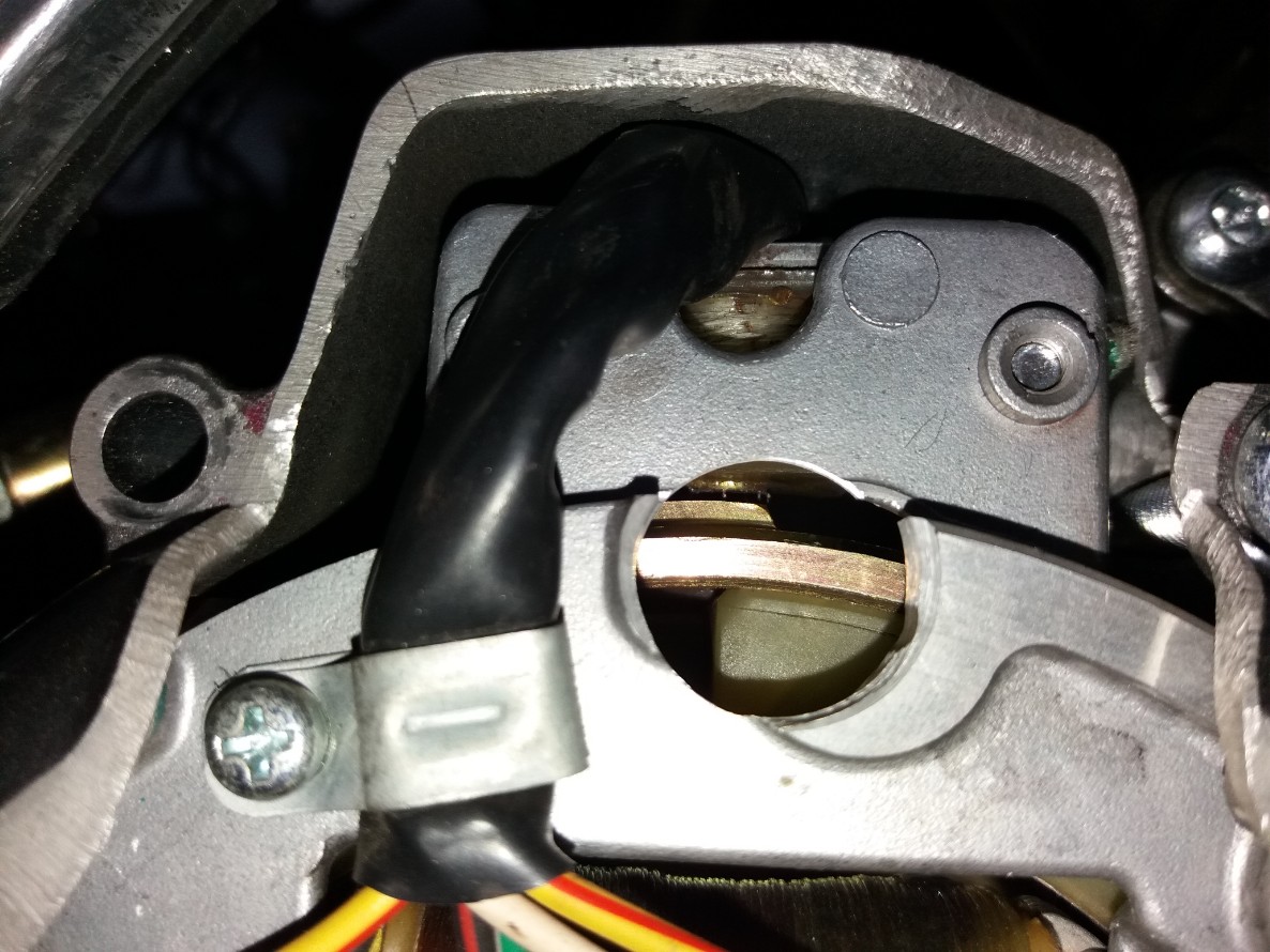
To see the end flywheel lob agenst the pickup center it needs a inspection point
Well her it is
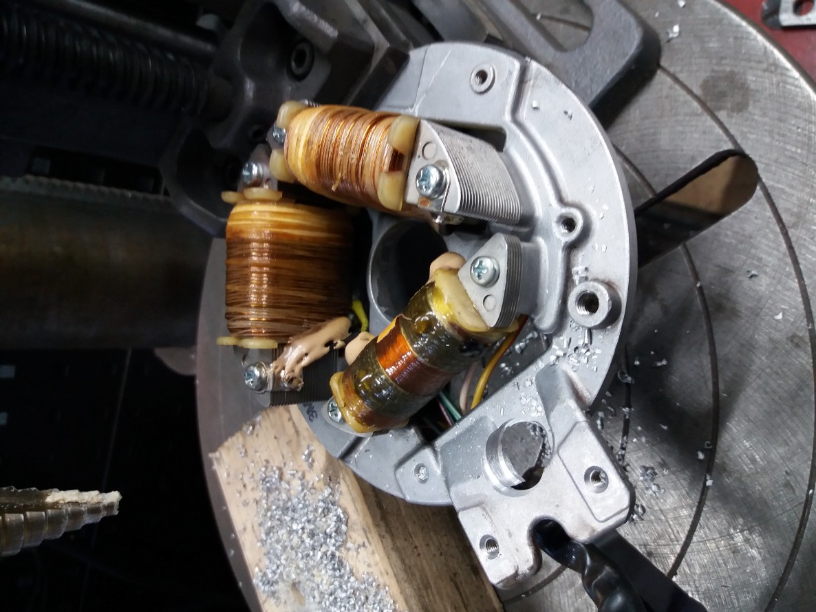
Here is the oem 4DL stator mounted with the inspection hole, with a timing clock
Measured 1,5mm from TDC to end flywheel lob
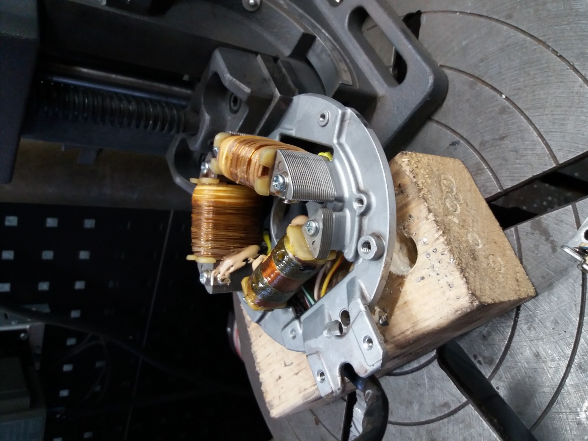
Next step will be to shorten the 4DL flywheel lob to match the location as a 3MA3 flywheel
Also need to balance the flywheel again du to the removed material
So far the info
4DL=1,5mm from TDC this is 17,88 degrees (logical as the ignition fires from a 4DL at the end of the lobe till +/-2500rpm at 18 degrees)
3MA=2,1mm from TDC this is 21,2 degrees (logical as the ignition from a 3MA3 fires at the end of the lobe till +/-2500rpm at 21 degrees
until now all good
Update 22-03-20
New plan, instead of shortening the lobe I tend to leave it like this (saves me balancing the flywheel)
We know that the 3MA CDI fires until +/-2000rpm at the back off the lob after that it goess to the front of the lobe to its programmed ignition curves.
Because the 4DL lobe is longer than the 3MA lobe this point will jump and can be seen with the timing light.
I only need to mark a firering point on the flywheel where it is marked 22 degrees (first start off the full throthle ignitioncurve for the 3MA3 CDI)
By turning the stator plate so the ignition fires at 22degrees (after firing point back off the lobe) I'll will have it spot on.
Well this is all theoretical we will see how it goes in practice.
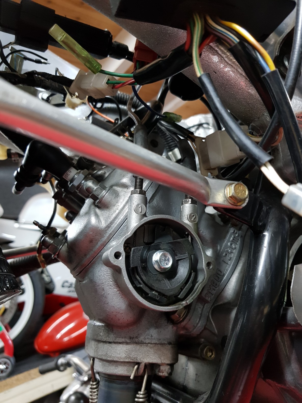
Made a bid space so I could turn the stator to both sides.
Must say it starts to get fragile, but this is only for testing, when it works will use an other side cover
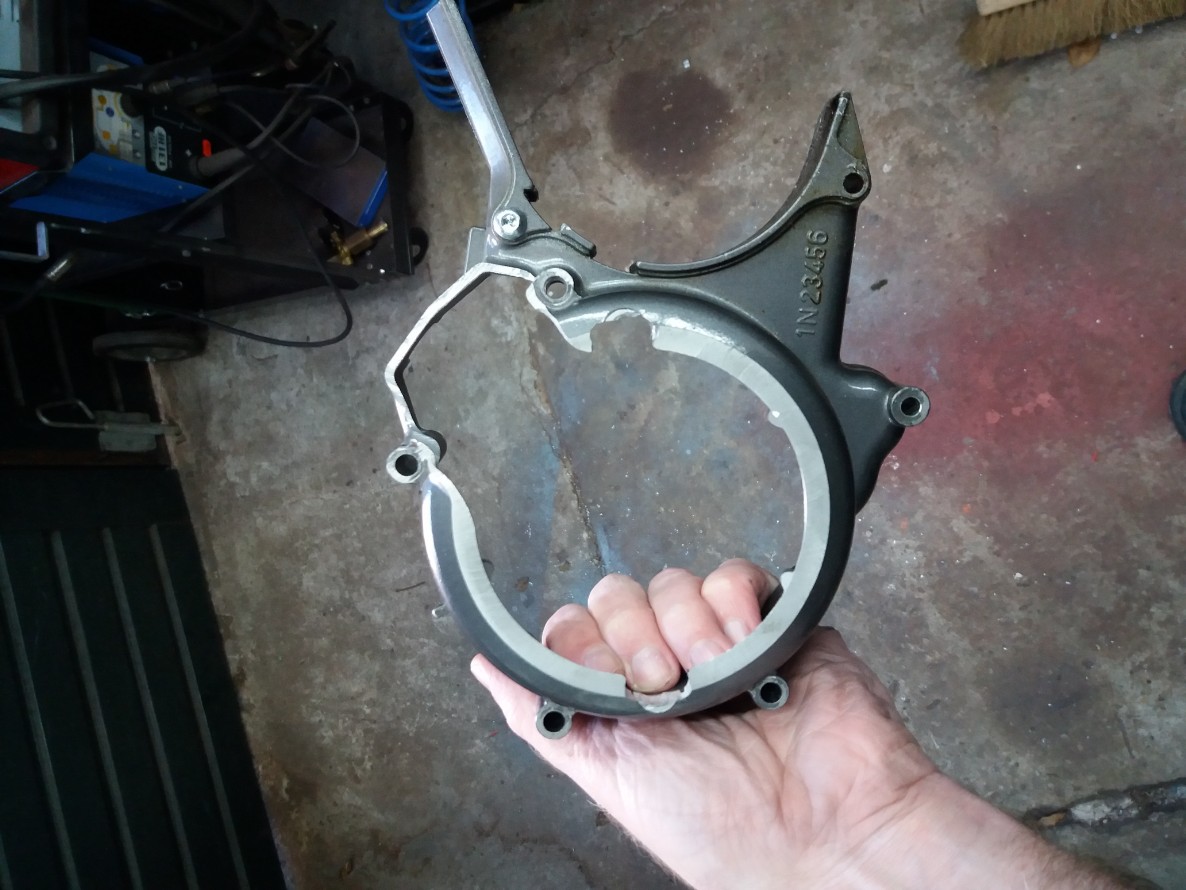
Well, now I can turn it clock and anti clockwise to get my 21 degree firing point
Next step is to connect it all and see how it goes
Update 23-03-2020
I have started on the new wiring loom, it wil only keep the necessary connections for all the components to work no mor no less.
Connections for:
1) CDI unit
2) Ypvs unit
3) TPS sensor
4) Speed limiter circuit
Lets start cutting
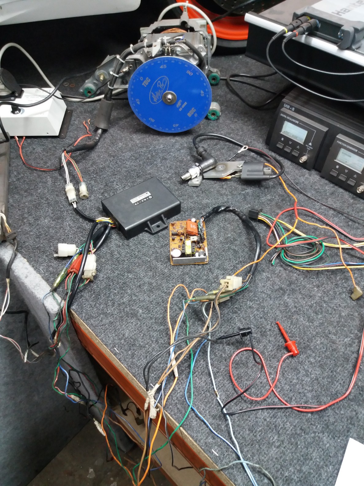
Connected both CDI's to a stock 3MA3 wiring loom to see which cables can be cut.
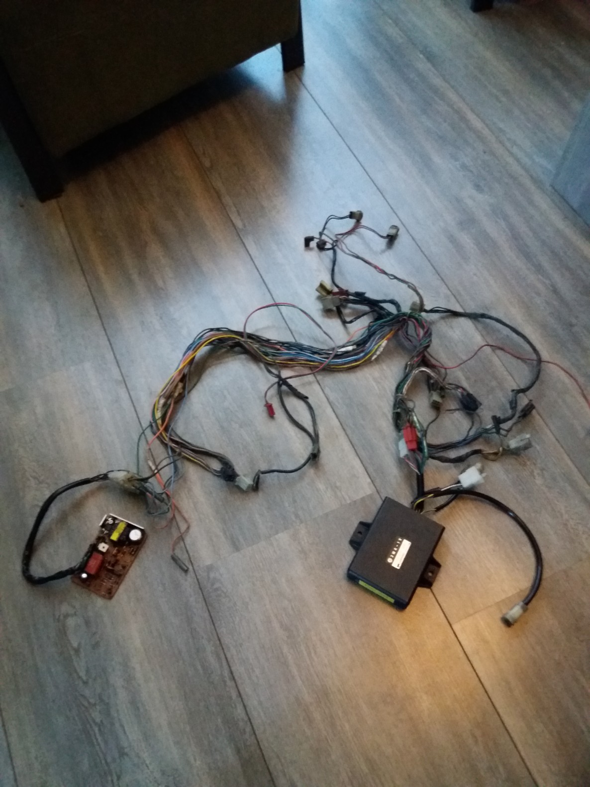
The result is a way tighter wiring loom, with only the essentials attached
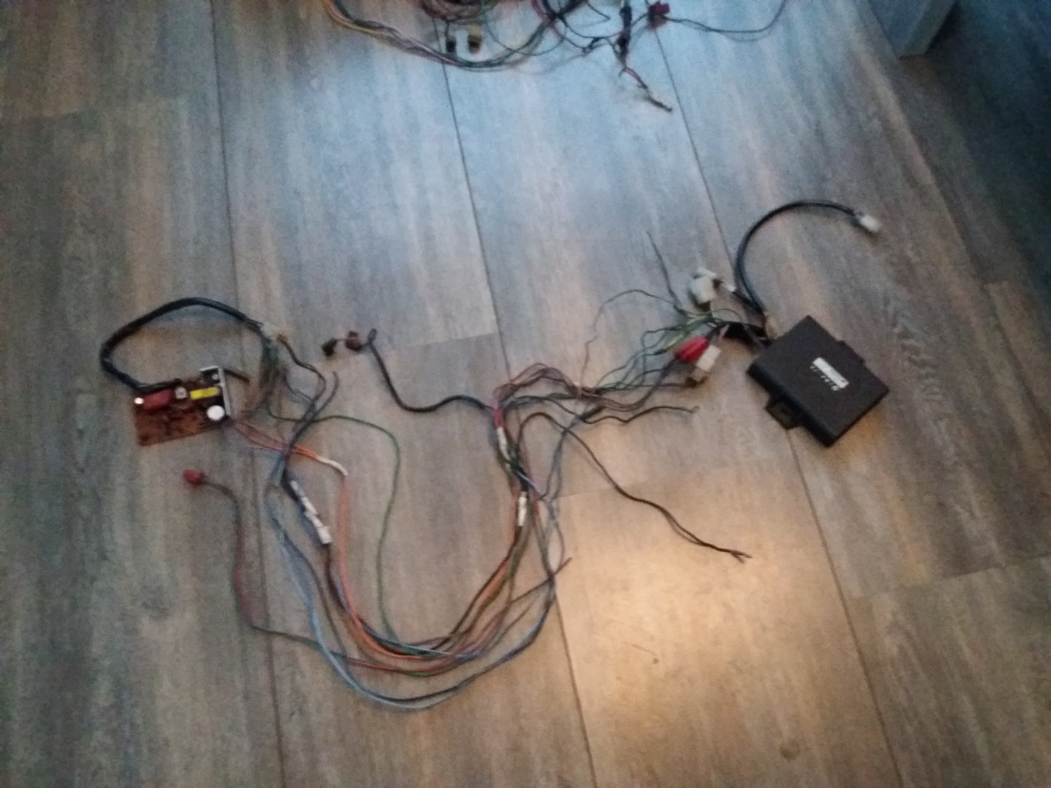
A quick testing run confirms that the right cables are cut, this system is working.
The next step will be to tighten it up, make it pretty again
Update 10-04-2020
Started with connecting it all this was relatively easy to do, the changed wiringloom seems to work as planned.
The big challenge seems to be turning the stator plate in order to get the right firing point.
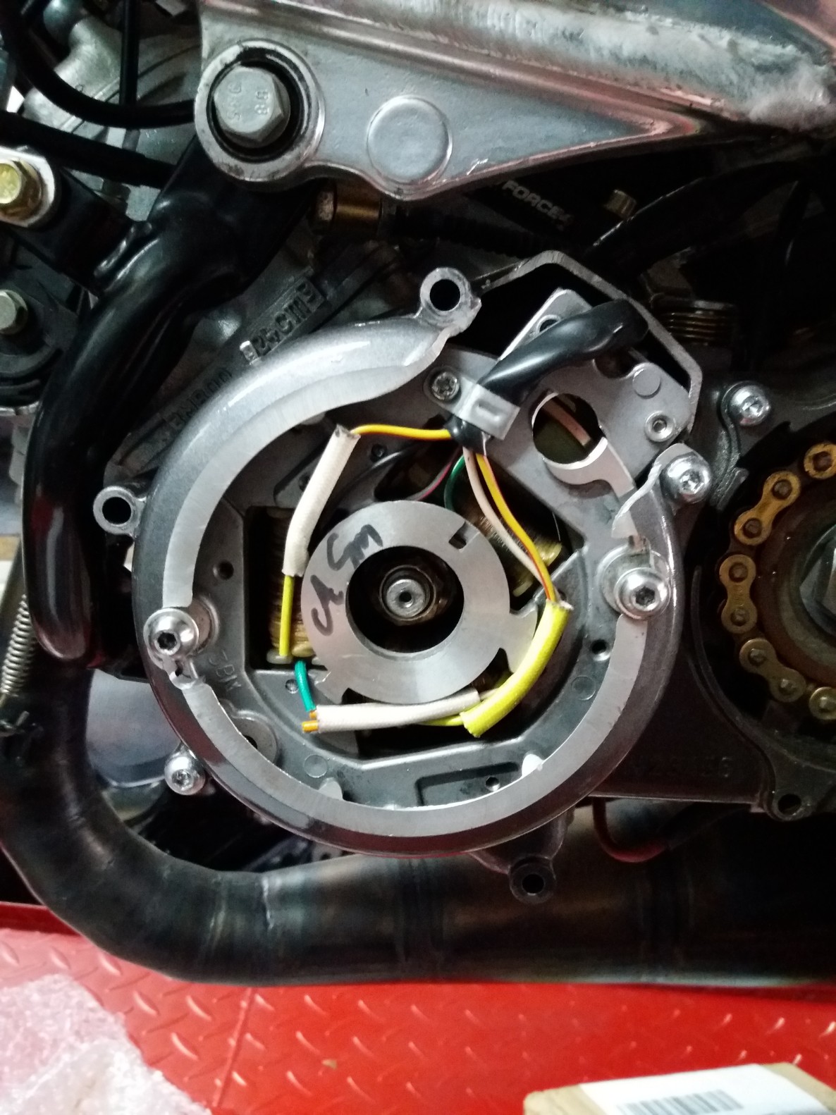
All wired up. (it will be made tidy of course, this is just for testing)
Here you can see where I started turning the stator plate end where I ended it. (as you can see it needed a lot)
Here you see my 22 degree mark (where ignition curve starts) and the 55 degree mark where the engine runs idle
Here's a shot with engine running at idle and with engine running at 22 degrees
Here she is running on 3MA3 electronics, the 55 degrees at idle is not idealistic but she is holding.
Have mounted the TZR3MA servo to work with the 3MA ignition
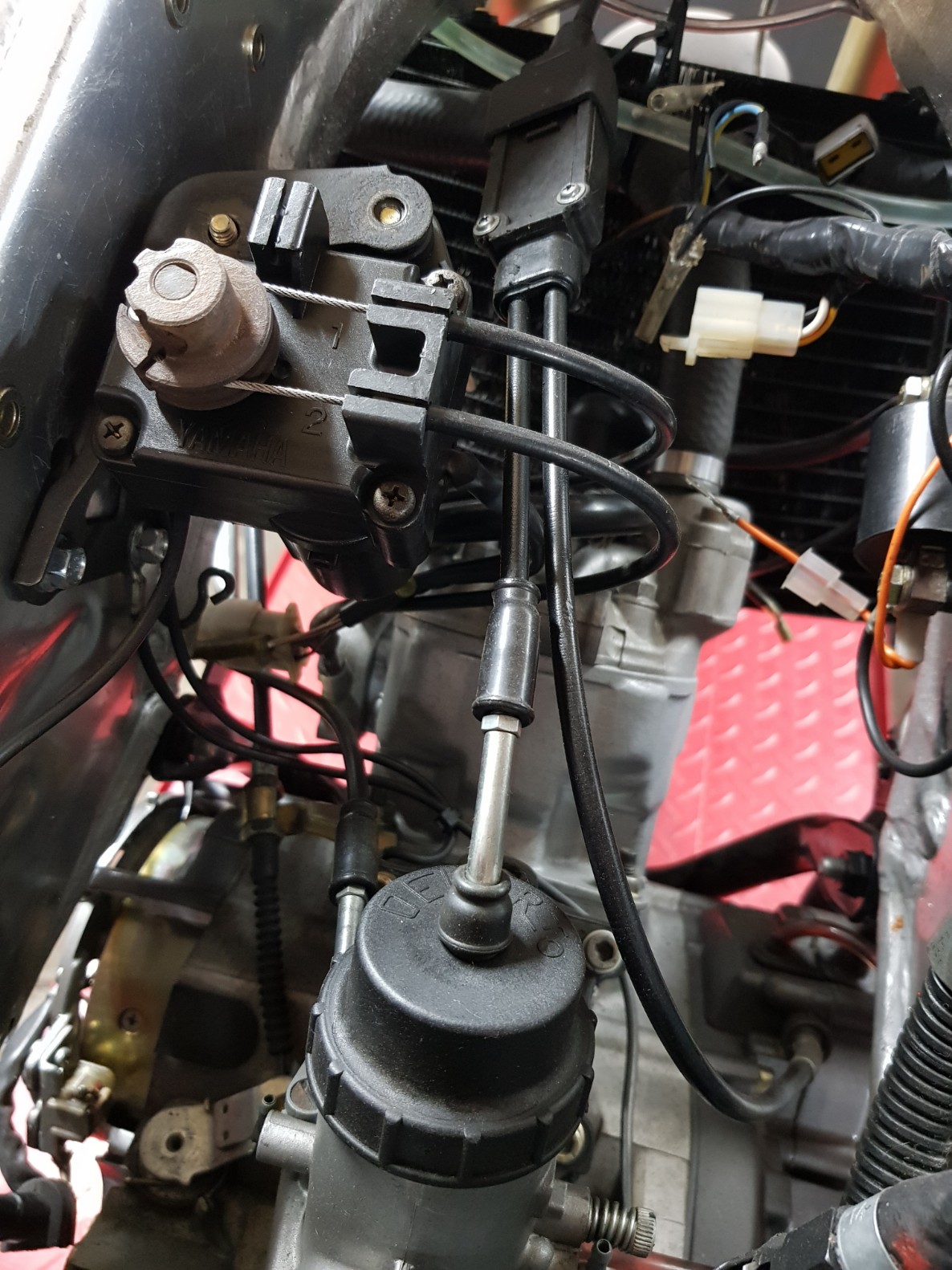
System is working well.